
MacMemoriesManager
Note: These are not the only options, nor are they guaranteed to work with your particular configuration, they are just the devices that I have had good luck with here at Dog Park Software Ltd. Links to the manufacturers sites are included. If you have specific cabling solutions that have worked for you, please send them in by email and I will be glad to include them in future releases of the manual.
While some of the latest radios (ie Kenwood TS-2000) have an RS-232 port built into the radio, most radios require a TTL-RS-232 level converter. The manual for your radio will usually include a reference to which (if any) level converter is needed.
The older Yaesu's use a FIF-232C

while some of the newer ones like the FT-817 use a CT-62 cable/level shifter.
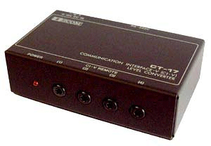
The icoms use a CT-17,
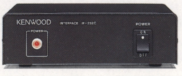
...and the Kenwoods use an IF-232C.
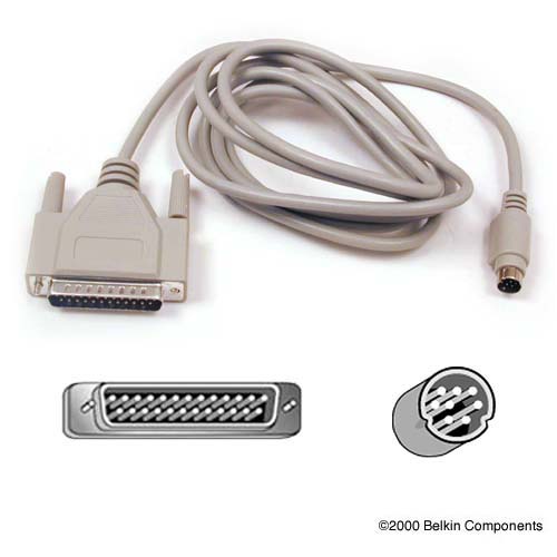
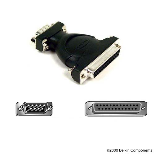
These level shifters assume an RS-232 connection to the computer, so if you are using a classic Macintosh RS-422 modem port or a Keyspan twin serial adapter with RS-422 ports you will need a Mac Modem cable to convert the RS-422 levels to RS-232.
If you want to home brew your own cable, see the section below on Macintosh Serial Port Hardware. The information here appears as a reference and a courtesy but Dog Park Software Ltd. does not guarantee the applicability to any specific installation. (Translation - please be carefull, I can not be held responsible if you let the smoke out of your radio interface or computer serial port).
microHAM has recently released combination USB/serial adapters and level converters:



The two serial ports of a Macintosh are mini-Din-8 connectors which are labeled with a telephone (the "modem port") and a printer ("printer port"). This is the pinout of the serial connectors. We are looking at the back of the Macintosh (or alternatively at the BACK of a male plug):
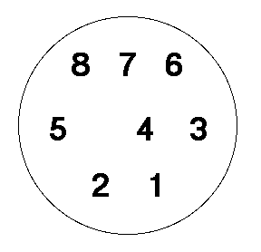
Note: this is looking at the back of the plug (into the socket - Space between 4 & 5)
| Pin | Signal | Description |
| 1 | HSKo | Output Handshake (Zilog 8530 DTR pin) |
| 2 | HSKi / Clock | Input Handshake or extern clk (Depending on 8530 mode) |
| 3 | TxD- | Transmit data (minus) |
| 4 | Ground | Signal ground |
| 5 | RxD- | Receive data (minus) |
| 6 | TxD+ | Transmit data (plus) |
| 7 | GPIn | General purpose input |
| 8 | RxD+ | Receive data (plus) |
Note this is a RS-422 interface so the signals come in a balanced pair, a positive (plus) and a negative (minus), for each data signal. As we shall see below, there is an easy method for matching this to RS-232. Also note that the General Purpose Input on pin 7 is not implemented on the Mac Plus or earlier machines.
We have given up soldering our own mini-Din-8 connectors. They cost $3.75 and they are just the pits to work with. We now buy 12 foot mini-Din-8 to mini-Din-8 cables for $10.00 from the Diskette Gazette people and cut them in half. Voila, two 6 foot mini-Din-8 to bare wire cables for $5.00 each. We solder on the DB-25 side and do the wire permutations there.
On the original 128K and the 512K upgrade machines (which have a DB-9 connector instead of the mini-Din-8) the Output Handshake line was held in a "marking" condition by hardware (a small resistor to the appropriate power supply rail). On later Macintoshes there are logic and a line driver for this line. This change introduces the following incompatabilities:
       DIN-8 MALE                       DB-25 MALE

       GROUND 4 O--+--------------------O 7  GROUND
  RECV DATA + 8 O--+

  RECV DATA - 5 O-----------------------O 3  RD (Receive Data)

  XMIT DATA - 3 O-----------------------O 2  TD (Transmit Data)

HANDSHAKE OUT 1 O--+
HANDSHAKE  IN 2 O--+--------------------O 20 DTR (Data Terminal Ready)
Note that in RS-232 the data signals are inverted (marking is minus) while the control signals are not (marking is plus). Thus the transmit data minus signal from the Mac is just right for driving the modem. Leave the transmit data plus signal disconnected. If you ground this you will short out a driver, and it will probably get hot. Similarly the receive data signal from the modem/DCE is inverted, so it can drive the Mac's receive data minus line, but in this case the receive data plus line is grounded to prevent any extraneous signals from being induced into the circuit.
Note also that we are driving both HSKi and DTR from HSKo so the problems described above can happen. An alternative arrangement would drive these signals from the modem/DCE's source of DSR, like this:
                                     +--O 6  DSR (Data Set Ready)
HANDSHAKE  IN 2 O--------------------+--O 20 DTR (Data Terminal Ready)
Some dumb modems might require Request To Send (RTS) which one would wire like this:
                                     +--O 6  DSR (Data Set Ready)
HANDSHAKE  IN 2 O--------------------+--O 20 DTR (Data Terminal Ready)
                                     +--O 4  RTS (Request To Send)
Finally, if you have only 3-wire cable and don't need DTR shutdown, you can wire each side to be happy like this:
HANDSHAKE OUT 1 O--+                 +--O 6  DSR (Data Set Ready)
HANDSHAKE  IN 2 O--+                 +--O 20 DTR (Data Terminal Ready)
                                     +--O 4  RTS (Request To Send)
       DIN-8 MALE                       DB-25 MALE

       GROUND 4 O--+--------------------O 7  GROUND
  RECV DATA + 8 O--+

  RECV DATA - 5 O-----------------------O 3  RD (Receive Data)

  XMIT DATA - 3 O-----------------------O 2  TD (Transmit Data)

HANDSHAKE  IN 2 O-----------------------O 5  CTS (Clear To Send)
This cable connects the modem's CTS back to the Macintosh's input throttle HSkIn so the modem can throttle the Macintosh as needed.
Many of the newer modems now do data compression and/or data rate conversion and so there is now a need for the computer and modem to be able to (temporarily) throttle output from each other. While there is a way defined in RS-232 for the modem to throttle the computer, there is no defined way for the computer to throttle the modem.
Vendors seem to have walked away from strict RS-232 in that they have redefined the meaning of the RTS (Request To Send) signal! This signal used to be used to tell the modem to acquire the communications medium for OUTPUT. Now it is being used to tell the modem that the computer is ready to take INPUT.
HANDSHAKE OUT 1 O-----------------------O 4 RTS (Request To Send [sic])
Thus this cable connects the Macintosh's ready signal HSkOut into the modem's RTS. Thus the Macintosh can throttle the modem when necessary. Depending on the program running on the Macintosh you may need to manually turn on handshaking by issuing the appropriate control call to the serial driver.
Lack of this wire usually causes the modem to be unable to send to the Macintosh. Sometimes the modem will ignore the signal when in command mode but require it when in data mode. The symptom here will be that the modem will answer commands and connect but will then act like the data receiver circuitry is disfunctional. If you need to know when the phone line is dropped (like for a bulletin board program that wants to know if it needs to ask for a password again) and you have a later model Macintosh that implements GPIn, you might want to wire DCD (Carrier Detect) into the general purpose input:
Gen Purp. In 7 O-----------------------O 8 DCD (Carrier Detect)
There is a Macintosh Technical Note describing the use of GPIn.
       DIN-8 MALE                      DB-25 FEMALE

       GROUND 4 O--+--------------------O 7  GROUND
  RECV DATA + 8 O--+

  RECV DATA - 5 O-----------------------O 2  TD (Transmit Data)

  XMIT DATA - 3 O-----------------------O 3  RD (Recieve Data)

HANDSHAKE  IN 2 O-----------------------O 20 DTR (Data Terminal Ready)
The same analysis applies with respect to the data signals, except that in this case the transmit and receive are switched around, since one guy's transmit should be the other guy's receive and vice versa. Note receive data plus is again grounded while transmit data plus is left disconnected.
For this particular cable we have wired the terminal/DTE's DTR back into the Macintoshes HSKi to implement a hardware handshake. Assume the terminal side is a printer that is being overrun. One of the things these printers can do is drop DTR. By wiring it through to the handshake input we make it possible for the Macintosh software to temporarily pause in sending, until the printer's buffers empty out and the printer reasserts the DTR signal.
Some terminal devices may need to see DSR (Data Set Ready) or CD (Carrier Detect) or CTS (Clear to Send), in which case they may be driven from an appropriate source.
                                     +--O 20 DTR (Data Terminal Ready)
This is probably appropriate         +--O 6  DSR (Data Set Ready)
for a communications terminal        +--O 8  CD  (Carrier Detect)
in which DTR is a totally static
signal and does not move.            +--O 4  RTS (Request To Send)
                                     +--O 5  CTS (Clear To Send)

or

                                     +--O 4  RTS (Request To Send)
This is probably appropriate	        +--O 6  DSR (Data Set Ready)
for a printer that flaps DTR         +--O 5  CTS (Clear To Send)
as the buffer fills and empties.     +--O 8  CD  (Carrier Detect)
The logic is to drive from whichever of DTR or RTS is NOT flapping around as buffers fill and empty or as the terminal transmits and receives...
On the DB-25 pin 1 is the FRAME ground and pin 7 is the SIGNAL ground. Equipment that requires connection to pin 1 is badly designed (IMHO). As a very last resort you might try a 1 to 7 jumper.
As you can imagine from seeing all these alternatives, an RS232 breakout box is real handy, since you can try all these patches without having to warm up a soldering iron. The only other thing I can say is:
Communications driver chips are built very ruggedly and will stand an amazing amount of mistreatment for a short period of time. But if you let two drivers fight for an hour one or both of them will burn out...
Ben Cranston <zben@ni.UMD.EDU>
Network Infrastructures Group
Academic Information Technology Services (formerly Computer Science Center)
University of Maryland at College Park
of Ulm